


Contact us
0769-85338950


TEL:0769-85338950
FAX:0769-85328216
EMAIL:lionpower@126.com
ADD:No.15, Jinxia huancun East Road, Chang'an Town, Dongguan City, Guangdong Province
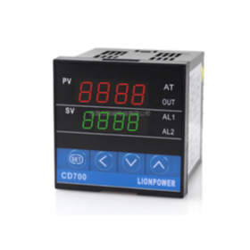
PID regulator
Encyclopedia business card
At present, the level of industrial automation has become an important indicator of the modernization level of various industries. At the same time, the development of control theory also experienced three stages: classical control theory, modern control theory and controllable theory. A typical example of intelligent control is a fuzzy fully automatic washing machine. Automatic control system can be divided into open loop control system and closed loop control system. A control system includes controllers, sensors, transmitters, actuators, input and output interfaces. The output of the controller is added to the controlled system through the output interface and actuator; the controlled quantity of the control system is sent to the controller through the input interface through the sensor and transmitter.

Introduction to regulator
English: PID regulator
Different control systems have different sensors, transmitters, and actuators. For example, pressure control systems use pressure sensors. The sensor of the electric heating control system is a temperature sensor. At present, there are many PID control and its controllers or intelligent PID controllers (instruments). The products have been widely used in engineering practice. There are various PID controller products. Major companies have developed PID controllers. An intelligent regulator with parameter self-tuning function, in which the automatic adjustment of PID controller parameters is realized through intelligent adjustment or self-correction and adaptive algorithms. There are pressure, temperature, flow, and liquid level controllers that use PID control, programmable controllers (PLC) that can realize PID control functions, and PC systems that can realize PID control. Programmable controller (PLC) uses its closed-loop control module to realize PID control, and programmable controller (PLC) can be directly connected to ControlNet, such as Rockwell's PLC-5. There are also controllers that can realize PID control functions, such as Rockwell's Logix product series, which can be directly connected to ControlNet and use the network to realize its remote control function.
PID principle
1. Open loop control system
The open-loop control system means that the output of the controlled object (the controlled quantity) has no effect on the output of the controller. In this kind of control system, it does not rely on returning the controlled quantity to form any closed loop.
2. The principle and characteristics of PID control
In engineering practice, the most widely used regulator control law is proportional, integral, and derivative control, referred to as PID control, also known as PID regulation. The PID controller has a history of nearly 70 years since it came out. It has become one of the main technologies of industrial control because of its simple structure, good stability, reliable work and convenient adjustment. When the structure and parameters of the controlled object cannot be fully grasped, or an accurate mathematical model cannot be obtained, and other techniques of control theory are difficult to adopt, the structure and parameters of the system controller must be determined by experience and on-site debugging. PID control technology is the most convenient. That is, when we do not fully understand a system and the controlled object, or cannot obtain the system parameters through effective measurement methods, PID control technology is most suitable. PID control, PI and PD control are also in practice. PID controller is based on the error of the system, using proportional, integral, and derivative to calculate the control quantity for control.
3. Step response
Step response refers to the output of the system when a step function is added to the system. Steady-state error refers to the difference between the expected output and the actual output of the system after the response of the system enters the steady state. The performance of the control system can be described in three words: stable, accurate and fast. Stability refers to the stability of the system. For a system to work normally, it must first be stable. From the step response, it should be convergent. Standard refers to the accuracy and control accuracy of the control system. Steady-state error is described, which represents the difference between the steady-state value of the system output and the expected value; fast refers to the rapid response of the control system, which is usually described quantitatively by rise time.
4. Closed loop control system
The characteristic of closed-loop control system is that the output of the controlled object (the controlled quantity) of the system will be sent back to affect the output of the controller, forming one or more closed loops. The closed-loop control system has positive feedback and negative feedback. If the feedback signal is opposite to the given value signal of the system, it is called negative feedback. If the polarity is the same, it is called positive feedback. Generally, closed-loop control systems use negative feedback. , Also known as negative feedback control system. There are many examples of closed-loop control systems. For example, a human is a closed-loop control system with negative feedback, and the eyes are sensors that act as feedback. The human body system can finally make various correct actions through continuous correction. If there is no eye, there is no feedback loop, and it becomes an open-loop control system. For another example, when a real fully automatic washing machine has the ability to continuously check whether the clothes are washed and automatically cut off the power after washing, it is a closed loop control system.
(1) Proportional (P) control
Proportional control is the simplest control method. The output of the controller is proportional to the input error signal. When there is only proportional control, the system output has a steady-state error (Steady-state error).
(2) Integral (I) control
In integral control, the output of the controller is proportional to the integral of the input error signal. For an automatic control system, if there is a steady-state error after entering the steady state, it is said that the control system has a steady-state error or simply a system with a Steady-state Error. In order to eliminate the steady-state error, an "integral term" must be introduced in the controller. The error of the integral term depends on the integration of time. As time increases, the integral term will increase. In this way, even if the error is small, the integral term will increase with the increase of time, which pushes the output of the controller to increase so that the steady-state error is further reduced until it equals zero. Therefore, the proportional + integral (PI) controller can make the system without steady-state error after entering the steady state.
(3) Differential (D) control
In derivative control, the output of the controller is proportional to the derivative of the input error signal (that is, the rate of change of error).
The automatic control system may oscillate or even lose stability during the adjustment process to overcome the error. The reason is that due to the presence of large inertial components (links) or delay components, which have the effect of suppressing errors, their changes always lag behind the changes in errors. The solution is to make the change of the effect of suppressing the error "leading", that is, when the error is close to zero, the effect of suppressing the error should be zero. That is to say, it is often not enough to introduce only the “proportional” term in the controller. The function of the proportional term is only to amplify the magnitude of the error. At present, the “differential term” needs to be added, which can predict the trend of error changes. In this way, the controller with proportional + derivative can make the control effect of suppressing errors equal to zero or even negative in advance, thereby avoiding serious overshoot of the controlled quantity. Therefore, for the controlled object with greater inertia or lag, the proportional + derivative (PD) controller can improve the dynamic characteristics of the system during the adjustment process.
PID controller parameter tuning
The parameter tuning of PID controller is the core content of control system design. It determines the proportional coefficient, integral time and derivative time of the PID controller according to the characteristics of the controlled process. There are many methods of PID controller parameter tuning, which can be summarized into two categories: One is the theoretical calculation tuning method. It is mainly based on the mathematical model of the system to determine the controller parameters through theoretical calculations. The calculated data obtained by this method may not be directly usable, and must be adjusted and modified through actual engineering. The second is the engineering tuning method, which mainly relies on engineering experience and is directly carried out in the test of the control system, and the method is simple and easy to master, and is widely used in engineering practice. The engineering tuning methods of PID controller parameters mainly include critical proportion method, response curve method and attenuation method. The three methods have their own characteristics. The common point is that they pass the test, and then adjust the controller parameters according to the engineering experience formula. But no matter which method is adopted, the controller parameters obtained need to be adjusted and perfected in actual operation. The critical ratio method is generally used now. Use this method to
The tuning steps of PID controller parameters are as follows:
(1) First, pre-select a short enough sampling period for the system to work;
(2) Only add the proportional control link until the critical oscillation appears in the system's step response to the input, and write down the proportional amplification factor and critical oscillation period at this time;
(3) Under a certain degree of control, the parameters of the PID controller are calculated through formulas.
Abbreviation for proportional integral differential regulator. Use the leading role of the proportional differential link to cancel the large inertia in the adjustment object, improve the accuracy, and speed up the dynamic response speed.
solid state relay
Encyclopedia business card
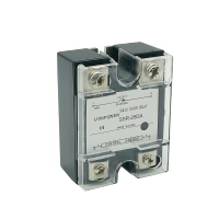
Solid State Relay (SSR) is a non-contact switch composed of microelectronic circuits, discrete electronic devices, and power electronic power devices. The isolation device is used to realize the isolation between the control end and the load end. The input terminal of the solid state relay uses a tiny control signal to directly drive a large current load.
【1】Introduction


For a control signal with a fixed control voltage, a resistive input circuit is used. The control current is guaranteed to be greater than 5mA. For control signals with a large variation range (such as 3-32V), a constant current circuit is used to ensure reliable operation of current greater than 5mA within the entire voltage variation range. Isolation drive circuit: The isolation circuit adopts optical-electrical coupling and high-frequency transformer coupling (magnetic-electrical coupling), photoelectric coupling usually uses photodiode-phototransistor, photodiode-bidirectional light-controlled thyristor, photovoltaic cell to realize control side and load Side isolation control. The high-frequency transformer coupling is that the self-excited high-frequency signal generated by the input control signal is coupled to the secondary, detected and rectified, and processed by the logic circuit to form the drive signal. The power switch of the SSR is directly connected to the power supply and the load side to realize the on-off switching of the load power supply. Mainly use high-power transistors (switching tube-Transistor), unidirectional thyristor (Thyristor or SCR), bidirectional thyristor (Triac), power field effect transistor (MOSFET), insulated gate bipolar transistor (IGBT) .Solid state relays can be easily connected with TTL and MOS logic circuits. The dedicated solid-state relay can have short-circuit protection, overload protection and overheating protection functions, and the combination logic solidification package can realize the intelligent module required by the user, which can be directly used in the control system.
Solid state relays are non-contact electronic switches with isolation function. There are no mechanical contact parts during the switching process. Therefore, solid state relays have the same functions as electromagnetic relays, but also have logic circuit compatibility, vibration resistance and mechanical shock resistance, and unlimited installation positions , It has good moisture-proof, mildew-proof and anti-corrosion performance, excellent performance in explosion-proof and ozone pollution prevention, low input power, high sensitivity, low control power, good electromagnetic compatibility, low noise and high operating frequency. It has been widely used in computer peripheral interface equipment, temperature regulation, speed regulation, dimming, motor control, electric furnace heating control, electric power and petrochemical, medical equipment, financial equipment, coal, instrumentation, traffic signals and other fields.
【2】the composition of solid state relays
The solid state relay is composed of three parts: input circuit, isolation (coupling) and output circuit. According to different types of input voltage, the input circuit can be divided into three types: DC input circuit, AC input circuit and AC/DC input circuit. Some input control circuits are also compatible with TTL/CMOS, positive and negative logic control, and reverse functions. The isolation and coupling of the input and output circuits of solid state relays are photoelectric coupling and transformer coupling. The output circuit of solid state relay can also be divided into DC output circuit, AC output circuit and AC/DC output circuit. For AC output, two thyristors or one bidirectional thyristor are usually used, and for DC output, bipolar devices or power FETs can be used.
【3】the advantages and disadvantages of solid state relays
1. The advantages of solid state relays
(1) Long life and high reliability: Solid state relays have no mechanical parts and solid components to complete the contact function. Because there are no moving parts, they can work under high impact and vibration environments. Because of the components that make up the solid state relay The inherent characteristics of solid state relays determine the long life and high reliability of solid state relays.
(2) High sensitivity, low control power, and good electromagnetic compatibility: The solid state relay has a wide input voltage range and low drive power, and is compatible with most logic integrated circuits without the need for buffers or drivers.
(3) Fast switching: Because solid-state relays use solid-state devices, the switching speed can range from a few milliseconds to a few microseconds.
(4) Small electromagnetic interference: The solid state relay has no input "coil", no arc ignition and rebound, thus reducing electromagnetic interference. Most AC output solid state relays are a zero-voltage switch, which turns on at zero voltage and turns off at zero current, reducing the sudden interruption of the current waveform, thereby reducing the switching transient effect.
2. Disadvantages of solid state relays
(1) The voltage drop of the tube after the turn-on is large, the forward voltage drop of the thyristor or two-phase thyristor can reach 1~2V, and the saturation voltage drop of the high-power transistor is also between 1~2V, general power field effect The on-resistance of the tube is also greater than the contact resistance of the mechanical contacts.
(2) The semiconductor device can still have a leakage current of several microamps to several milliamperes after it is turned off, so ideal electrical isolation cannot be achieved.
(3) Due to the large pressure drop of the tube, the power consumption and heat generation after the conduction is also large, the volume of the high-power solid-state relay is much larger than the electromagnetic relay of the same capacity, and the cost is also higher.
(4) The temperature characteristics of electronic components and electronic circuits have poor anti-interference ability and poor radiation resistance. If effective measures are not taken, the working reliability will be low.
(5) Solid state relays are more sensitive to overload and must be protected against overload with fast fuse or RC damping circuit. The load of the solid state relay is obviously related to the ambient temperature. As the temperature rises, the load capacity will drop rapidly.
(6) The main disadvantages are the on-state voltage drop (corresponding heat dissipation measures are required), off-state leakage current, AC and DC cannot be used universally, the number of contact groups is small, and overcurrent, overvoltage, voltage rise rate, current rise rate, etc. Poor indicators.
3. Precautions for solid state relays
(1) When selecting solid state relays used on printed circuit boards with low current specifications, since the lead terminals are made of high thermal conductivity materials, the soldering should be carried out under the conditions of a temperature less than 250℃ and a time less than 10S, such as considering the surrounding temperature. If necessary, derating can be considered. Generally, the load current should be controlled within 1/2 of the rated value.
(2) Selection of solid state relay SSR for various load surge characteristics
The controlled load will generate a large inrush current at the moment of switching on. Because the heat is too late to dissipate, it is likely to damage the SSR internal thyristor. Therefore, the user should analyze the surge characteristics of the controlled load when selecting the relay, and then Select the relay. Make the relay can withstand this surge current under the premise of ensuring steady-state operation. When selecting, refer to the derating factor of various loads in Table 2 (under normal temperature).